Create animations using Plastic tool
Plastic is a powerful tool ( ) that can be used as complement in a cutout animation context, as well as a stand-alone animation tool capable of bringing to life a character starting from a single drawing. Using a reference skeleton and a deformable mesh, Plastic allows to curving and deforming each element it’s applied to, creating smooth animations.
Using Plastic tool
The Plastic tool needs as starting input at least one column of the Xsheet (or layer of the Timeline) where one or more drawings are exposed; from now on this will be referred to as the texture-column (or TC). Using the outlines of the exposed drawing/s as references, the Plastic tool generates a triangular mesh contained in a new kind of column/layer: the Mesh column/layer. Each newly created Mesh column/layer is automatically connected to the proper TC. This link is a core point in the way Plastic works: every column/layer linked to a mesh will be deformed by it, and displayed within the mesh boundaries while rendering.
For animating/deforming a Mesh level, Plastic allows the building of a specific skeleton structure active on the mesh. The skeleton is a set of connected vertices, and, for each vertex, different parameters can be specified as: Position, Angle Bounds, Rigidity and Staking Order. Thus a great range of animations and effects can easily be created.
Note
The Plastic tool is applied to a column of the Xsheet (or layer of the Timeline), and the content of it can be an animated level.
Building a Plastic mesh
The first step for using Plastic is creating a mesh for the Xsheet column (or Timeline layer) that we are going to animate using the Plastic tool. The Mesh is a special kind of level, and can be saved as any other kind of levels.
The Mesh level can be seen as purple column/layer created when the button Create Mesh of the Plastic tool is pressed.
The mesh is the real object that the Plastic tool modifies when a plastic skeleton is animated. For this reason all the elements, that are going to be animated by the Plastic tool, need a mesh.
Tip
To create a Plastic mesh:
Select the column/layer that is going to be animated using the Plastic tool. This will be the texture-column (TC) of the mesh that is going to be created.
Choose the Plastic tool (
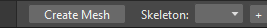
)Press the Create Mesh button in the tool options bar.
Check, in the dialog that opens, the Mesh density in the preview area. Adjust as needed the density using the Mesh Edges Length slider.
Note
The density of the mesh is crucial for having smooth curves when rotating the skeleton vertex. Lower the Mesh Edges Length value and higher the density of the mesh will be, thus a better quality of the animation will be assured, but more computing resources will be required.
Note
The preview will show you just one level at time, even if you have selected multiple columns/layers, to check the preview of each column/layer you have to select them one by one while the Plastic tool is active. Each time you change the column/layer selection the preview will update for the new content.
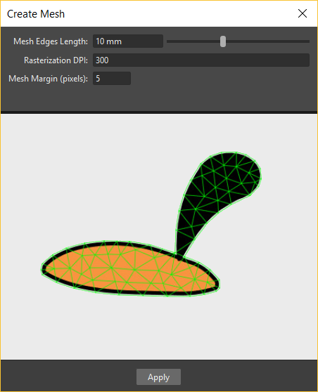
If needed, change the value of the Rasterization DPI parameter. This value represents the DPI used when the TC is rendered as a texture for the mesh. It’s recommend using a value consistent with the Camera resolution. A DPI too high compared to the Camera resolution might cause the contours of the TC not to be very soft.
Note
The Rasterization DPI parameter is available only when you are creating the mesh from Vector levels.
Adjust the Mesh Margin value. This parameter is expressed in pixels because it’s used when the texture is projected on the mesh, an appropriate amount of margin will be needed to preserve the aliasing of the picture.
If you are creating a mesh from a Subscene, you can choose which elements of the Subscene will be used by the Plastic tool for computing the mesh: simply turn off visibility for the elements that will not contribute to the mesh outline.
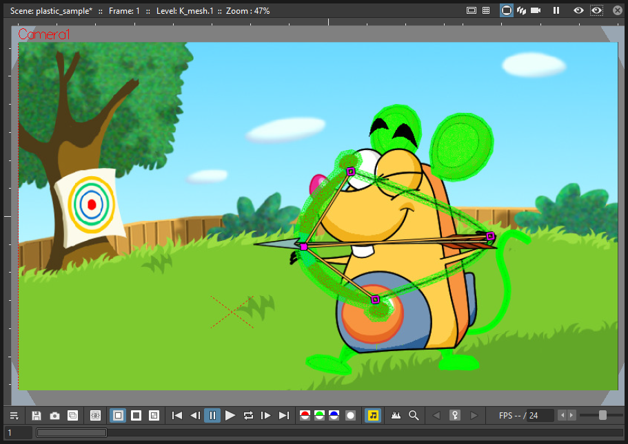
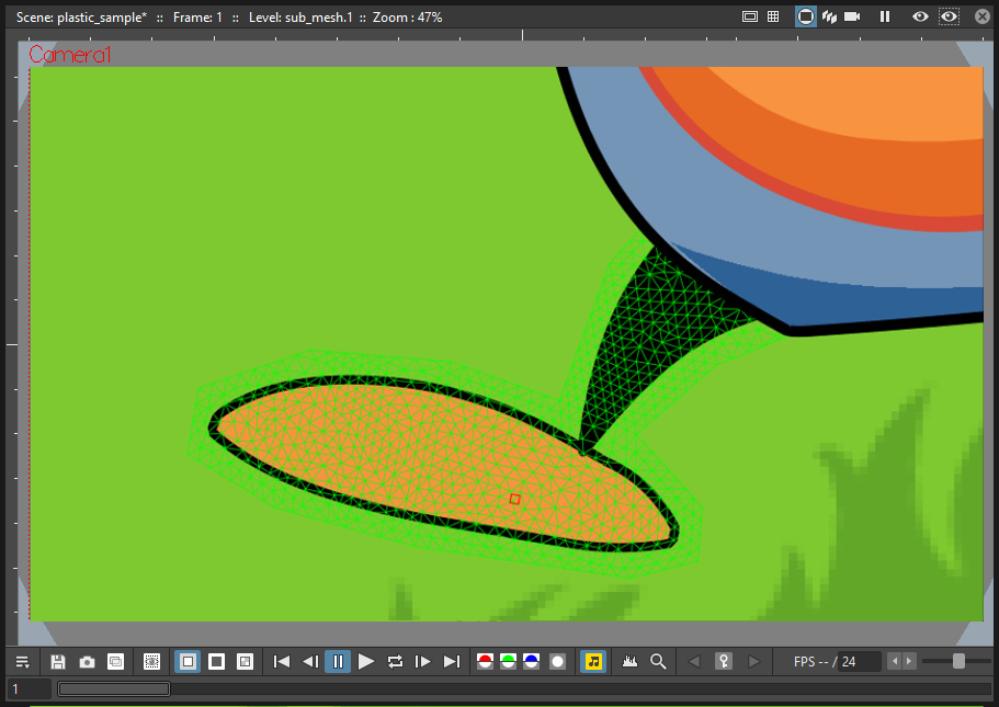
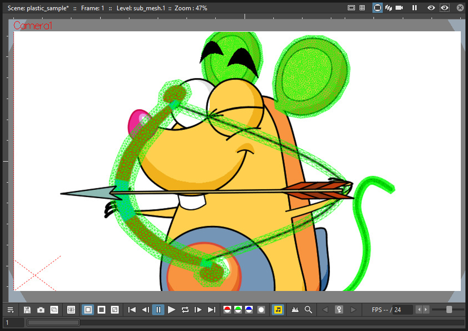
Click the Apply button to create the mesh. Now you can see the mesh drawn in green colour in the Viewer, and a new purple column in the Xsheet (or layer in the Timeline) next to the TC.
Note
In the Stage Schematic you can see that the TC node is now connected to the Mesh node just created, its node has a purple header for easing recognition.
If the Create Mesh is applied to a column/layer that is already modified by the Plastic tool (then already linked to a Mesh level) a dialog will prompt asking how to manage the new and the old Mesh files, and the user can choose from one of three options:
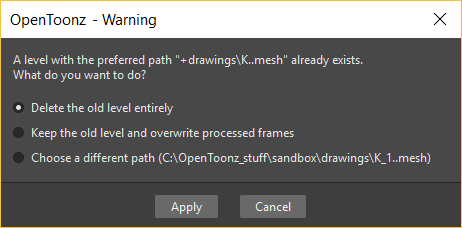
Delete the old level entirely : the original mesh file is replaced by a new one with the data of the last mesh generated; a new column for the new mesh is created as the old column retains the old structure but exposes only the new created mesh.
Keep the old level and overwrite processed frames : the original mesh file is updated and the old mesh column exposes the new content for the selected frames, a new column is created exposing just the contents of the selected frames.
Choose a different path (same name as the original level plus _X where X is the ordinal number of the copy): an entirely new mesh file is generated and a new column exposes the new contents while the old column exposes the old ones.
Note
All the above options cause the creation of a new Mesh column and the building of a chain, linking the texture-column and the meshes columns in the Stage Schematic. In this chain, the older mesh is linked to the younger and the youngest mesh is linked to the texture-column. Rearranging the links in the Stage Schematic can be needed for avoiding undesired results while animating.
Modifying a Plastic mesh
It’s not always easy to estimate the right density for a mesh. Sometimes a higher density could be needed to avoid straight lines on bending elements, or a lower density could be used for saving computing resources in a complex scene, or, simply, the drawings of an element are changed. In all this occurrences, modifying the mesh can solve the problem.
Tip
To update a Plastic mesh to reflect changes in the Level Strip:
Select the Mesh column/layer that needs to be modified.
Press the Create Mesh button.
In the dialog that opens change the Mesh Edges Length slider value as needed, checking the result in the preview area.
Click the Apply button to create the mesh. The new mesh replaces the old one, and now is visible drawn in green colour in the main viewer.
Tip
To add new mesh frames to an existing mesh level:
Select the Mesh column/layer that needs to be modified.
Create the new frames (inserting or appending them) as it’s usually done for any standard Toonz level, corresponding to the new frames created for the Texture Column.
Activate the Plastic tool.
Press the Create Mesh button and adjust the Mesh Edges Length slider.
Press the Apply button.
Edit a Plastic mesh
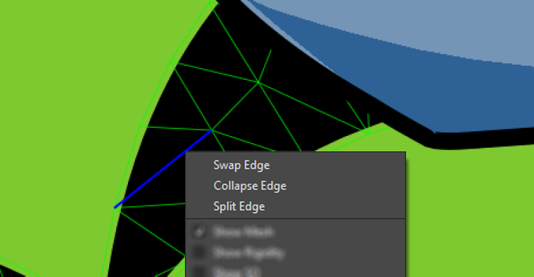
The mesh created using the Create Mesh button can be edited in several ways. It’s possible to: Move a mesh point, Swap, Collapse, Split and Cut the mesh by its edges.

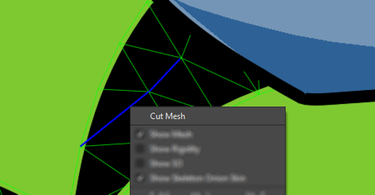
Swap an edge if you want to change the shape of a mesh triangle; Collapse an edge if you want to join the ends of the edge; Split an edge if you want to increase the density of the mesh at any given point; Cut the mesh if you want to duplicate an edge to have the possibility, for example, to create a hole in the mesh and be able to animate it.
Note
The Cut Mesh command is visible only if the selected edges can be cut.
Tip
To enter Plastic mesh editing mode:
Select the mesh column/layer you want to modify.
If not already active, choose the Plastic tool (
)In the Tool Options bar set the Mode: to Edit Mesh.
Tip
To move selected mesh points:
Select the mesh points you want to modify. Use the Ctrl key to select multiple points. Selected mesh points become red.
Drag to move the point to its new position.
Tip
To swap an edge of the mesh:
Select a mesh edge.
Click the right mouse button to open the context menu.
Choose the Swap Edge command.
Tip
To collapse an edge of the mesh:
Select a mesh edge.
Click the right mouse button to open the context menu.
Choose the Collapse Edge command.
Tip
To split an edge of the mesh:
Select a mesh edge.
Click the right mouse button to open the context menu.
Choose the Split Edge command.
Tip
To cut edges of the mesh:
Select several mesh edges.
Click the right mouse button to open the context menu.
Choose the Cut Mesh command.
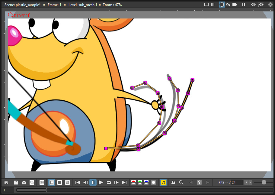
Building a Plastic skeleton
The Plastic skeleton is a control structure linked to a mesh level that provides handles for deforming/animating the chosen elements of the Xsheet/Timeline.

Tip
To create a Plastic skeleton:
Select in the mesh column/layer for which you want to build the skeleton.
If not already active, choose the Plastic tool (
)In the Tool Options bar set the Mode: to Build Skeleton.
Move the mouse pointer on the Viewer. A small red square is now visible near the tip of the cursor.
In the Viewer click (to set in place) or click and drag (to adjust its positioning) to place the first vertex. A purple square is now visible in the Viewer.
Note
The first time you release the mouse button, you are setting the position of the parent of all the hierarchy, the Root vertex. This vertex differs visually from the others vertices: its square is solid while the others are hollow in the middle, giving a visual hint for determining the right hierarchical order in the skeleton chains. The Root vertex will be static in Animate mode, but it can still be moved while in Build Skeleton mode by selecting it and dragging.
Move to the position where you want to add the second vertex and click or click and drag to place it. An orange line with a black border will connect the two vertices.
Continue clicking or clicking and dragging until all the vertices are in the right places and the skeleton is completed.
Using multiple skeletons on a mesh level
Every mesh level uses at least one skeleton for animating, but this is just the easier configuration for working: a mesh level can have multiple skeletons active at different frames for building more complex animations: like a character turn-around, or for animating a level with multiple drawings of different shapes. Every time the drawings change in shape, a new ad-hoc skeleton structure can be built with the number of vertices needed and placed in the right positions.

Tip
To add a new skeleton on a mesh level
In the Xsheet/Timeline select the Mesh level and the frame where the new skeleton is needed.
In the Tool Options bar press the + button to the right of the options menu labeled Skeleton:. A new numeric entry is added to the list and a keyframe is created at the selected frame.
Start building the new skeleton as usual.
Tip
To link an available skeleton to a chosen frame of a mesh level
In the Xsheet/Timeline select the frame of the Mesh level where the skeleton has to change.
In the Tool Options bar open the option menu labeled Skeleton:, a list of the ID numbers of the already built skeletons opens.
Select the ID number matching the skeleton you need.
The selected skeleton is now visible in the main Viewer, and a keyframe is created at the chosen frame.
Tip
To delete a skeleton from the Skeleton list
In the Xsheet/Timeline select the Mesh level owning the skeleton that has to be deleted.
Select from the Skeleton: drop down the ID matching the skeleton to delete.
Press the - button.
Modifying a Plastic skeleton
While drawing the skeleton or after finishing its creation, some adjustments to the positions or the number of vertices may be required:
Tip
To Select a vertex:
While in Build Skeleton mode, move the mouse pointer on an already placed vertex.
Click, when the name of the vertex appears and a dashed square encloses the vertex position.
Tip
To Delete a vertex:
While in Build Skeleton mode, select the vertex that has to be deleted.
Press the Del key.
Tip
To Insert a vertex:
While in Build Skeleton mode, move the mouse pointer over the line connecting the two vertices that need a vertex between them.
Click to set the new vertex in place, or click and drag to adjust the position of the new vertex.
Tip
To Move a vertex:
Click on the vertex to select it, and drag for adjusting its position.
Tip
To Prevent a vertex from Stretching the mesh:
Select the vertex that you wish to modify.
Uncheck the Allow Stretching option in the Tool Options bar.
Note
The square marking the vertex position becomes yellow, and from now on the vertex will not stretch the Mesh while you are moving it.
Tip
To Snap a vertex to the mesh
While in Build Skeleton mode, activate the Snap To Mesh option.
Select the vertex you wish to snap.
Drag it near the mesh point at which you want to snap it.
Tip
To Branch the skeleton:
While in Build Skeleton mode, select the vertex from which the new branch will start.
Move to the position where the first vertex of the new branch will be positioned.
Click to create it.
Tip
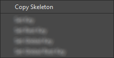
To Copy a skeleton:
While in Build Skeleton mode, select the Root vertex and click the right mouse button.
From the context menu that opens, select the Copy Skeleton option.
Tip
To Paste a skeleton:
Select a mesh column in the Xsheet/Timeline.
If needed press the + button to create a new empty skeleton.
Click the right mouse button and select the Paste Skeleton option.
Note
Pasting the skeleton on an already existing one will cause the deletion of the old structure and all its animation. This can be reverted to the previous state by using the Undo command.
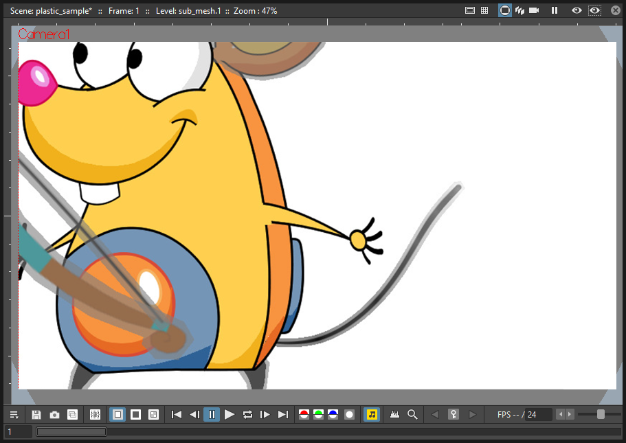
Animating Plastic elements
Creating an animation in Plastic is quite an easy task: just select the vertices and move them to the desired positions at a specific frames and animation keyframes will be automatically created. Play back the sequence to check the results.

Tip
To animate Plastic elements:
Select the mesh column/layer you like to animate.
Select Plastic tool and set Mode: to Animate. Now, in the Viewer, you can see the skeleton and the mesh of the selected column/layer.
Select the first frame of the animation in the Xsheet/Timeline.
Select the vertices of the skeleton and move them to the desired positions to set the relative keyframes, or write the desired values into the text fields of the Tool Options bar.
Move to the next keyframe of the animation and modify the vertices positions to define a new pose.
Repeat the step 5 until the end the animation is finished.
Tip
To Set a Rest Position key for one vertex:
The first time you draw a skeleton you are also creating the rest position of this structure. This pose is automatically stored and you can recall it on any vertex.
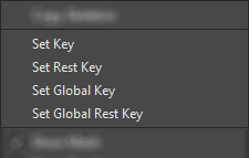
Select a vertex and click the right mouse button.
From the context menu that opens, select Set Rest Key.
A new keyframe at the current frame is created for the vertex, using its rest values.
Tip
To Set a Global Rest Position key for the whole skeleton:
The first time you draw a skeleton you are also creating the rest position of this structure. This pose is automatically stored and you can recall it on all the vertices.
Select a vertex and click the right mouse button.
From the context menu that opens, select Set Global Rest Key.
A new keyframe at the current frame is created for all the vertices, using their rest values.
Tip
To preserve the distance between vertices while animating:
If it’s required that the distance between two joints stays constant during the animation, check the Keep Distance checkbox in the Tool Options bar.

Tip
To Set Keyframes on all vertices at the same time:
By default when you move a vertex in Animate mode, you set a keyframe just for this selected vertex. For setting a keyframe simultaneously for all the vertices of the skeleton, when just moving one of them, check the Global Key checkbox.
Tip
To Set a Keyframe for a vertex which hasn’t changed position:
Select the vertex for which you want to create a keyframe.
Click the right mouse button.
Select the Set Key option from the context menu that opens.
Tip
To Set a Keyframe for all the skeleton vertices which hasn’t changed position:
Select a skeleton vertex.
Click the right mouse button.
Select the Set Global Key option from the context menu that opens.
Tip
To animate the Stacking Order of a vertex:
Using Plastic you can simulate the effect of overlapping limbs defining a stacking order for the vertices involved in the animation.
Select the vertex you wish to animate.
Input the Stacking Order value you wish to assign to the vertex into the SO text field in the Tool Options bar.
Note
Plastic stacking order is a per vertex characteristic, you have to define the value you wish for each vertex required. The default value is 0 for all vertices, and can be modified freely using positive or negative values as needed.
Tip
To define an Angle Bounds for a vertex:
Select the desired vertex.
Set the minimum and maximum Angle Bounds values for the vertex rotation.
Defining Rigidity for a Plastic mesh
In many occasions it may be required that certain portions of a Mesh that’s being animated using the Plastic tool, preserve their shape even if following the overall transformations of the whole element, simulating a more rigid structure or a part of it. To achieve this kind of effect a Rigidity value can be painted directly on the Mesh.

When activating the Paint Rigid mode in the Plastic Tool Options bar, a specific drawing tool becomes available. In the Viewer a red circle is visible near the tip of the mouse pointer, the size of the circle is the size of the brush you are going to use for painting the rigidity on the mesh.
Tip
To paint Rigidity on a mesh:
Select the mesh column/layer in the Xsheet/Timeline.
Choose the Plastic tool (
)Set the Mode: to Paint Rigid.
Set the size of the brush moving the Thickness slider or entering a value into the text field.
Select Rigid from the option menu to the right of the Thickness slider (Rigid is the default value).
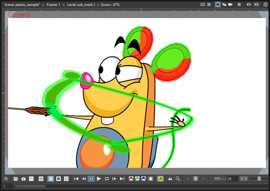
Move the cursor on the Viewer and start painting on the selected Mesh. The colour of the mesh will change to red where painted. Now the red areas behave as rigid portions of the Mesh.

Tip
To modify, correct, erase Rigidity on a mesh:
Select the mesh column/layer in the Xsheet/Timeline.
Choose the Plastic tool (
)Set the Mode: to Paint Rigid.
Set the size of the brush moving the Thickness slider or entering a value into the text field.
Select Flex from the option menu to the right of the Thickness slider.
Move the cursor on the Viewer and start painting on the selected Mesh. The colour of the mesh will change to green where painted. Now the green areas behave as flexible portions of the Mesh.

Note
The default colour of a mesh is green; it means that the whole mesh is flexible. The red colour is used to point out the rigid areas of the mesh (if there are any defined). But if a mesh is all painted in red colour it behaves as a flexible one too.
Displaying Plastic elements and properties
While working with the Plastic tool there is an easy way for customizing which information have to be displayed in the Viewer. Clicking the right mouse button on the Viewer while the Plastic tool is active brings up a context menu. There are four checkboxes that set the display properties for the Mesh, the Rigidity, the SO (Stacking Order) and the Skeleton Onion Skin.
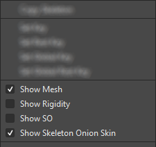
If Show Mesh is enabled, the mesh will be visible as a triangulated wire frame shape.
If Show Rigidity is enabled, continuous green areas will show the flexibility, while red areas will show rigidity.
If Show SO is enabled a grey shading shows the Stacking Order values of the vertices, where lighter areas will be on top, and darker ones behind.
If Show Skeleton Onion Skin is enabled, ghosts of the skeleton at the selected frames will be displayed with incremental levels of transparency.
All of this information can be displayed at once (by checking all the options), giving an overall description of the vertices state.
Parenting Plastic levels using vertices and hooks
For building interesting and complex animations it could be useful and time saving to create a hierarchical relationship between standard levels and Plastic modified levels, or between Plastic modified levels themselves, so that the children levels inherit the transformations of the parent automatically. It’s always possible to link the levels using the column/layer center as target, but what if something more subtler is needed as using Hooks? We have already described similar techniques for Tahoma standard elements (see Linking Objects or Using Hooks ), but Plastic modified levels works in a slightly different way because the Hook tool is not enabled on this kind of levels. Plastic modified levels use their skeleton vertices instead of the hook points.
Tip
To link a standard level to a Plastic modified level
Select in the Xsheet/Timeline the level that has to be linked.
Use the Hook tool in the Viewer to create a hook on the spot that will be used as pivot for the level.
Go to the Stage Schematic and select the node of the column/layer that has to be linked. Click on the small square on its left side, and drag to one of the small squares on the right side of the Plastic modified node target of the link. Now the two levels are linked but the reference points for the link are probably wrong (by default the column/layer centers are used).
Hover on the small square on the left side of the node of the standard level until two small arrows (pointing up and down) appear.
Click on the arrows and drag to change the value in the small square. Stop when the number of the hook point that has to be used as pivot point is reached. In the Viewer the level moves using the chosen point as new center.
Do the same procedure of point 5 on the small square on the right of the Plastic modified node that was used as target for the link. Select the number of the skeleton vertex that has to be used as target reference point for the link. Into the Viewer the standard level moves to overlap the position of the hook point selected as reference to the position of the skeleton vertex selected on the Plastic modified level.
Note
A mirror procedure can be used for linking a Plastic modified level to a standard level.
Tip
To link Plastic modified levels
The procedure requires that all the levels involved and that need to be linked using determined positions, have at least one skeleton built and one of its vertices has to be positioned at the desired spot for the linking. As said, the Hook tool doesn’t work on the Plastic modified levels so, for exact positioning, skeleton vertices are needed as reference points both on the source and on the target of the link.
Go to the Stage Schematic and select the node of the column/layer that has to be linked. Click on the small square on its left side, and drag to one of the small squares on the right side of the target of the link. Now the two levels are linked but the reference points for the link are probably wrong (by default the column/layer centers are used).
Hover on the small square on the left of the node of the first node until two small arrows appear.
Click on the arrows and drag to change the value in the small square. Stop when the number of the skeleton vertex point that has to be used as pivot point is reached. In the Viewer the level adjusts its position in respect of the new selected center.
Do the same procedure of point 3 on the small square on the right of the Plastic modified node that was used as target for the link. Select the number of the skeleton vertex that has to be used as target reference point for the link. Into the Viewer the first level moves to overlap the position of its selected skeleton vertex to that of the target skeleton vertex just selected.
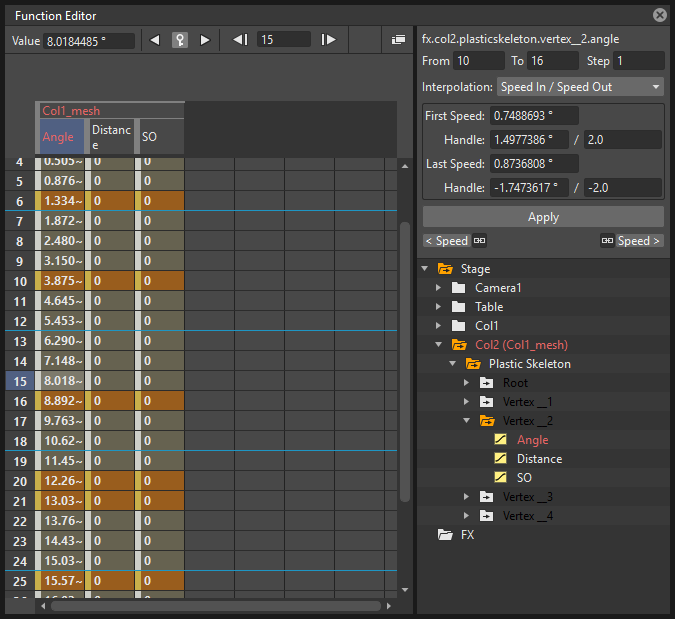
Function Editor representation of Plastic data
While animating Plastic elements, keyframes are created for the vertices of the skeleton. You can see them as standard keyframes in the Xsheet/Timeline, or you can operate on the values of each vertex into the Function Editor.
The keyframess of the Xsheet/Timeline mark a keyframe for the Plastic skeleton at the specified frame, but don’t give any information about the number of vertices involved or their actual keyframed properties; they can be indifferently, one, some or all. Moving these keyframes you can easily change the timing of the whole animation.
The keyframes into the Function Editor are more detailed, giving you the chance for fine-tuning and modify each vertex parameter animation.
When in the Function Editor Tree, you open the folder of a column/layer that has the Plastic tool applied, you can see a Plastic Skeleton folder. This folder contains the Skeleton Id channel, the Root subfolder, and one subfolder for each vertex of the Plastic skeleton, labeled with the name of the related vertex.
The Skeleton Id channel contains the data related to which skeleton is active at a certain frame. If the level is using multiple skeletons here you can see the switches from one skeleton to the other, both as numeric values and in a graphical format.
The Root subfolder shows all the parameter channels, but only the SO (Staking Order) parameter can be animated when this vertex is actually used as root of the skeleton
The Vertex subfolders (one for each vertex of the skeletons), contain three parameters: Angle, Distance and SO, that are used to determine the position of the vertex at every frame during the animation.
The values of these parameters can be visualized in the Function Editor as a spreadsheet or as curves, and modified as required.
Note
The vertices of multiple skeletons are shown as a single list, and not grouped for each skeleton. In this way the animation curve of Vertex_1 is built using the animation values of the vertices named Vertex_1 of all the skeletons of the mesh, so just one curve can be modified to adjust the animation of related vertices on different skeletons.
Use Mathematical Expressions in Plastic Animation
To use Tahoma mathematical expressions in the Plastic Animation, you can link the vertices of the skeleton to each other or to a column/layer, pegbar or camera.
This allows to set some automatic actions of the skeleton, for example you can link the main vertices of the shoulders, so that moving just one shoulder automatically moves the other.
Suppose that the main vertices of the shoulders are named Shoulder_left and Shoulder_right, and the Mesh is in column 2 of the Xsheet (or layer 2 of the Timeline). You can set the rotation of Shoulder_left vertex to be the same amount of that of Shoulder_right, by setting in the Function Editor the following expression in the Angle parameter of Shoulder_left:
vertex(2, "Shoulder_right").angle
If you prefer the rotation of the left shoulder to react opposite to the one of the right shoulder, you could add a multiplication as following:
vertex(2, "Shoulder_right").angle*-1
The general syntax is:
vertex(column_number, “vertex_name”).parameter
For more information about the mathematical expressions usage refer to (See Using Interpolations Based on Expressions ).
Plastic and Subscenes
A Subscene is a valid object for the Plastic tool, and all or some of its columns can have a mesh for animating. When a Subscene is selected as a starting element, all of the columns in the Subscene visible when the Create Mesh button is pressed, are taken into count for the creation of the Mesh. These levels will be visible in render and will be deformed by Mesh transformations. If, after creating the Mesh, hidden levels are set to visible, they will behave in a slightly different way: they will be deformed by Mesh transformations, but they will be shown in render only inside the mesh boundaries (i.e. the Mesh acts as a mask that determines what is visible in the rendered image, even if the newly-shown levels are placed into a nested Subscene with its own mesh and skeleton).