Painting Animation Levels
Toonz animation levels, both those cleaned up, and those made directly in Tahoma, can be painted by using the styles, stored in the palette, and a set of tools.
All Toonz level drawings are made of lines (determined by the strokes of scanned or vector drawings), and areas defined by closed lines. Raster and vector lines can be painted or erased, partially or for their full extent; areas can be filled with styles, or remain empty, with complete transparency.
Note
All the painting work is not saved until you save the related level, or use the Save All command (see Saving Levels ).
Note
If the computer performance worsens during the painting process of Smart Raster animation levels, try activating the Minimize Raster Memory Fragmentation option in the Preferences → General dialog (see Optimizing the Memory Usage ).
Painting Tools
Painting operations can be performed by using the Fill tool ( ) and the Paint Brush tool (
 ).
).
In case you want to retrieve a style already used in the drawing, you can pick it with the Style Picker tool ( ).
).
The filling operation can be performed by activating different options, that can be combined together to perform particular tasks, for example to fill several areas at the same time with the same style, or several frames, with a single operation.
The Fill tool () allows you to paint a drawing area or line by clicking it. Options available are the following:
Type: has the options Normal, to fill an area by clicking in it; Rectangular, to fill all the areas included in the box you define; Freehand, to fill all the areas included in the area you outline by clicking and dragging; and Polyline, to fill all the areas included in the area you outline by defining a series of lines.
Mode: has the options Areas, to fill only areas, Lines, to paint only the strokes, and Lines and Areas, to perform both operations.
Selective prevents the fill operation to be performed on already filled areas.
Fill Depth sets how much the fill style passes through the antialiasing of the area lines. With low values, even a very thin line made of semitransparent pixels will be effective to stop de filling operation; with high values, only the more opaque pixels will stop color from flooding outside. This option applies to Smart Raster drawings only. It is possible to set two values: the minimum value is used when using the tool with the standard mouse click, the maximum value when using the tool with the Shift-click.
Segment lets you apply the fill only to a segment of raster lines. A segment is determined by an abrupt change of thickness or direction in the stroke. This is available for Smart Raster drawings only.
Onion Skin lets you pick the style to use for the filling operation from other drawings, visible in onion skin mode, and apply it to the current drawing (see Using Onion Skin ).
Frame Range allows you to perform the filling on a range of frames, by clicking in the first and then in the last frame of the range. You can also Shift-click to define the filling position for intermediate frames.
The Paint Brush tool () allows you to paint a drawing area or a line, as if you were using a brush. It is available for Smart Raster drawings only. Options are the following:
Size sets the brush size.
Mode: has the options Areas, to paint only inside areas, Lines, to paint manually only the drawing lines, and Lines and Areas, to perform both operations.
Selective prevents the painting operation to be performed on already painted areas.
Filling Areas
Areas can be filled when their outline is well-defined, with no gaps occurring along it. For vector drawings, the outline can be defined by a single vector with overlapping or joined ends, or by different vectors.
Options available for the painting tools can help you to speed up the painting job. You can decide which options are the most suitable for your task by following the guidelines below.
Note
In Smart Raster levels, the areas that can be painted are limited either by the image border or by the image Savebox, according to the Use the TLV Savebox to Limit Filling Operations option available in Preferences → Tools.
Note
Some styles may not be suitable for filling areas, such as the Trail or Vector styles or some of the Generated styles. If you select one of these styles in the Palette, and you use it to fill an area, no operation will be performed.
Tip
To fill an area:
Select the Fill tool (
), set the fill type to Normal and the mode to Areas, and select a style in the Palette.Click in the area you want to fill.
Note
If the filling color doesn’t flood the narrowest areas in raster drawings because of semitransparent pixels, try to increase the minimum Fill Depth value, or Shift-click to use the maximum value (see Painting Tools ).
Tip
To fill several frames with a single command:
Select the Fill tool (
), set the fill type to Normal and the mode to Areas, and activate the Frame Range option.Select the first frame of the range and click in the area you want to fill, for example the character’s face.
Do one of the following:
Select the last frame of the range you want to apply the Fill to, and click in the same area, in the example the character’s face: the areas in all of the frames in the range will be automatically filled according to the first and second clicking positions.
Select an intermediate frame of the range you want to apply the Fill to, and Shift-click in the same area, in the example the character’s face: the areas in all of the frames in the range will be automatically filled according to the first and second clicking positions. Select another intermediate frame and Shift-click again: the areas in all of the frames in the new range will be automatically filled according to the second and third clicking positions. Do the same as many times as you like, then click in the same area on the last frame of the range to complete the multi frame filling mode.
Note
Since the Fill with the Frame Range option is applied making a linear interpolation from the first clicking point to the following one, some painting mistakes may occur. The more the area you want to fill moves along the frame range, the more mistakes may be made.
Tip
To fill several areas at once with the same style:
Select the Fill tool (
), set the fill mode to Areas.Do one of the following:
Set the type to Rectangular and click and drag to define a box: all the areas completely included in the box will be filled with the current style.
Set the type to Freehand and click and drag to outline an area: all the areas completely included in the area you outline will be filled with the current style. If the ends of the outline you draw are open, the area will be defined as if joining the two open ends.
Set the type to Polyline and click to outline an area by defining a series of lines: all the areas completely included in the area you outline will be filled with the current style. If the ends of the outline you draw are open, the area will be defined as if joining the two open ends.
Tip
To fill all remaining areas in a level drawing with the same style:
Select the Fill tool (
), set the fill type to Rectangular and the mode to Areas, and activate the Selective option.Click and drag to define a box: all the outlined non-filled areas completely included in the box will be filled with the current style. This option combination may be useful if the drawing has a lot of areas to be painted with the same style, that can be painted at the end at once by using this command.
Note
You can add to this combination the Frame Range option as well, to perform the same task extended to a range of frames.
Tip
To fill drawing areas using as reference a previously painted drawing:
Activate the onion skin mode to display the painted drawing behind your current drawing (see Using Onion Skin ).
Select the Fill tool (
), set the fill mode to Areas and activate the Onion Skin option.Click to pick the style to use from the drawing displayed in onion skin mode.
Do one of the following:
Release to fill the area where the cursor is.
Drag to the area you want to fill and release the mouse button.
Note
If several drawings are displayed in onion skin mode, only the drawing closest to the current one will be considered.
Tip
To automatically fill a whole drawing using as reference a previously painted drawing:
Activate the onion skin mode to display the painted drawing behind your current drawing (see Using Onion Skin ).
Select the Fill tool (
), set the fill type to Rectangular, the mode to Areas, and activate the Onion Skin option.Click and drag to define a box: all the areas completely included in the box will be filled with the styles picked from the painted areas of the drawing displayed in onion skin mode.
Note
If several drawings are displayed in onion skin mode, only the drawing closest to the current one will be considered.
Note
If some areas are automatically painted with the wrong style, fix them to prevent the mistake to be amplified in the following frames you are going to paint.
Tip
To retrieve a style from a drawing:
Select the Style Picker tool (
).Click in the area whose style you want to pick. The picked style becomes the current one.
Closing Gaps in Drawing Outline
If the area outline is not perfectly defined, you will not be able to fill it. The gap can be closed by adding a line with the Brush ( ) or Geometric (
 ) tools (see Drawing Tools ), or by using the Tape tool (
 ).
).
For Vector drawings the Tape tool () allows you to join vector strokes manually or automatically, both considering their endpoints and any point along the strokes themselves, according to the tool settings. Options available are the following:
Type: has the options Normal, to manually define joining vectors, or Rectangular, to automatically close all the gaps detected in the box you define.
Note
When the type is set to Rectangular only gaps between endpoints, and between an endpoint and a line, are considered.
Mode: has the option Endpoint to Endpoint, to join two lines endpoints; Endpoint to Line, to join an endpoint to any point along a line; and Line to Line, to join any point along a line to any other point along another line.
Distance sets the maximum distance between endpoints, and between an endpoint and a line, that are automatically joined when using the Rectangular option.
Join Vectors, when activated, connects the join stroke to the endpoint thus creating a single stroke; if deactivated the join stroke will be a new independent stroke (see Joining and Splitting ).
Note
If the strokes you are going to join have different styles, the style of the first stroke you click on will be assigned to the second one, after the joining.
Smooth, when activated, creates a smooth joined stroke with no corners.
For Smart Raster drawings the Tape tool () automatically joins the open ends detected in the drawing according to the tool settings. Options available are the following:
Type: has the options Normal, to close all the gaps detected in the drawing by clicking in it; Rectangular, to close all the gaps detected in the box you define; Freehand, to close on all the gaps detected in the area you define by clicking and dragging; and Polyline, to close on all the gaps detected in the area you define by drawing a series of straight lines.
Frame Range allows you to perform the joining on a range of frames, by clicking in the first and then in the last frame of the range.
Distance sets the maximum distance between two open ends to be detected, in order to join them.
Angle sets the maximum angle between two open ends to be detected, in order to join them.
Style Index sets the style to be used for the line joining the open ends. If instead of a style index you type
current, the currentntly selected style will be used.Opacity sets the opacity of the style used for the line joining the open ends.
Note
Please note that by default Opacity value is set to 1, and with this value the gap will be closed using a transparent line that will not be seen in the Viewer. Also, note that the value of this option will equally affect how the Gap Check function is displayed in the Viewer.
Tip
To close a gap in a vector drawing outline:
Select the Tape tool (
), set the type to Normal and set whether to join vectors, or to create a smooth joining.Do one of the following:
Set the mode to Endpoint to Endpoint, then click a stroke endpoint and drag to a different endpoint; the pointer snaps to the closest detected stroke endpoint, as start and end.
Set the mode to Endpoint to Line, then click a stroke endpoint and drag to any point along a stroke; the pointer snaps to the closest detected stroke endpoint as start, and to any closest point along a stroke as end.
Set the mode to Line to Line, then click any point along a stroke and drag to any other point along a stroke; the pointer snaps to the closest point along a stroke as start, and to the any other closest point along a stroke as end.
Tip
To close all gaps in a vector drawing outline in a specific area:
Select the Tape tool (
), set the type to Rectangular.Click and drag to define an area: all the gaps between endpoints, and between endpoints and lines, detected in the area according to the set distance will be closed.
Tip
To close all gaps in a raster drawing outline:
Select the Tape tool (
).Click in the viewer to close all the gaps detected according to the set distance and angle.
Tip
To close a specific gap in a raster drawing outline:
Select the Tape tool (
) and activate the Rectangular option.Click and drag to define an area: all the gaps detected in the area according to the set distance and angle will be closed.
Checking Gaps in the Drawing Outline
To control the drawing outline and see if areas are well-defined in order to be filled with colors, it is possible to activate a series of checks:
The Gap Check highlights with magenta lines the gaps that can be automatically closed by using the Tape tool (
) with its current settings; if you change the Distance and Angle values of the Tape tool, while the check is activated, you can check interactively if the gaps that are detected.
Note
Please note that the Tape tool Opacity value will affect the display of the Gap Check in Smart Raster levels, so if it is set to the default value of 1, you will not be able to see anything with the Gap Check function. Set it to 255 instead, to be able to use this check.
The Fill Check displays all the well-defined areas that can be filled with colors in grey, all the lines or vector strokes in black, and the not well-defined areas and the background in white; if the Black BG Check is activated, all the lines or vector strokes are displayed in white (see Checking Painted Drawings ).
Note
All the checks can also be combined in order to achieve specific display modes (see also Checking Painted Drawings ).
Tip
To check if gaps occur in the drawing outline:
Activate or deactivate the Gap Check from the View menu.
Tip
To check if the areas in the drawing are well-defined:
Activate or deactivate the Fill Check from the View menu.
Checking Painted Drawings
To control if all the drawings areas are properly painted, and to see if the filling left small gaps along the lines antialiasing, or where a certain style is being used to paint lines or areas, it is possible to activate a series of checks:
The Transparency Check displays all the painted areas in the color defined in Preferences → Colors → Paint Color, all the lines or vector strokes in the color defined in Preferences → Colors → Ink Color on White Bg (or Preferences → Colors → Ink Color on Black Bg, depending on the chosen background color).
The Ink Check displays the lines or vector strokes, colored with the current style in red.
The Paint Check displays the areas painted with the current color in red.
The Black BG Check displays the background color, defined in the Scene Settings, in black (see Customizing the Viewer ).
Note
All the checks can also be combined in order to achieve specific display modes (see also Checking Gaps in the Drawing Outline ).
Tip
To activate or deactivate a check:
Activate or deactivate the check from the View menu.
Painting Lines
Lines of a drawing can be painted with the Fill tool ().
For Smart Raster drawings, the Fill tool () affects continuous lines sharing the same style; for Vector drawings, only a single vector stroke at a time.
For Smart Raster drawings, lines can be also painted with the Paint Brush tool () set to Lines mode. In this case by setting the size of the tool, you can paint any section of the lines as if you were using a brush.
For Vector drawings, a vector stroke can be also painted by selecting it first, then selecting the style you want in the level Palette.
Tip
To paint a Smart Raster line:
Select the Fill tool (
), set the fill mode to Lines and select a style in the palette.Click the line you want to paint.
Tip
To paint a Vector stroke:
Do one of the following:
Select the Fill tool (
), set the fill mode to Lines, select a style in the Palette and click the stroke you want to paint.With the Selection tool (
 ) select the strokes you want to paint, then select a style in the Palette (see Using the Selection Tool ).
Tip
To partially paint a Smart Raster line:
Do one of the following:
Select the Fill tool (
), set the fill mode to Lines, activate the Segment option, and click the line section you want to paint.Select the Paint Brush tool (
), set the mode to Lines and use it on the line section you want to paint.Use the Paint Brush tool (
) with the proper style to split a continuous line into sections, then use the Fill tool () to paint the previously separated sections.
Tip
To paint several separated lines or vector strokes, at once:
Select the Fill tool (
), set the fill mode to Lines.Do one of the following:
Set the type to Rectangular and click and drag to define a box: all the lines included in the box will be painted with the current style.
Set the type to Freehand and click and drag to define an area: all the lines included in the area you defined will be painted with the current style. If the ends of the area you draw are open, it will be defined as if joining the two open ends.
Set the type to Polyline and click to define an area by drawing a series of straight lines: all the lines completely included in the area you defined will be painted with the current style. If the ends of the area you draw are open, the area will be defined as if joining the two open ends.
Note
A vector stroke will be painted only if it’s fully included in the area you define.
Tip
To paint lines or vector strokes, in several frames with a single command:
Select the Fill tool (
), set the fill mode to Lines and activate the Frame Range option.Select the first frame of the range and click the line you want to paint.
Do one of the following:
Select the last frame of the range you want to apply the paint to, and click on the same line: the line in all the frames in the range will be automatically painted according to the first and second clicking positions.
Select an intermediate frame of the range you want to apply the paint to, and Shift-click in the same line: the line in all of the frames in the range will be automatically painted, according to the first and second clicking positions. Select another intermediate frame and Shift-click again: the line in all of the frames in the new range will be automatically painted, according to the second and third clicking positions. Do the same as many times as you like, then click in the same line on the last frame of the range, to complete the multi frame painting mode.
Note
Since the Fill tool () with the Frame Range option is applied making a linear interpolation from the first to the second clicking point, some painting mistakes may occur. The more the line you want to fill moves along the frame range, the more mistakes may be made.
Tip
To paint a line using as reference a previously painted drawing:
Activate the onion skin mode to display the painted drawing behind your current drawing (see Using Onion Skin ).
Select the Fill tool (
), set the fill mode to Lines and activate the Onion Skin option.Click to pick the style to use, from the drawing displayed in onion skin mode.
Do one of the following:
Release to paint the line where the cursor is.
Drag to the line you want to paint and release the mouse button.
Tip
To retrieve a style from a drawing:
Select the Style Picker tool (
).Click the line whose style you want to pick. The picked style becomes the current one.
Using Match Lines
Sometimes it may be useful to split a hand-drawn animation level into several animation levels that can be scanned separately, and later re-assembled before the painting process. For example you can draw an animation level with some shadow lines that match perfectly a character animation, then apply them with a color different from the character lines in order to paint them more easily.
Some other times you may need to merge two or several animation levels into a single one, or automatically add the same drawing on all of the drawings of an animation level, for example a line closing the drawing areas that fall outside the shot and that the animator left open.
In both cases you can use the match lines feature to achieve your tasks, as it allows you to merge the levels exposed in two columns/layers, and if needed to delete the merged match lines.
Match lines can only be applied to Smart Raster (TLV) animation levels.
In the Xsheet, when two columns are merged, the column drawings on the right are considered as match lines applied to the drawings on the left (in the Timeline, when two layers are merged, the layer drawings on top are considered as match lines applied to the drawings on the bottom).
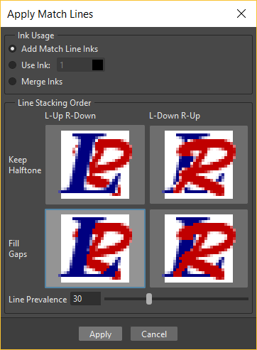
In both cases it’s possible to define the following:
Add Match Line Inks preserves the original match line styles and adds them to the destination level palette in a separate page named match lines.
Use Ink: allows you to define which style, among those in the destination level palette, has to be used for the applied match lines, replacing any original styles the match lines may be painted with.
Merge Inks if the target level has the same styles (i.e. with the same index and color) as the match lines inks, the existing styles will be used. Otherwise, the original match line styles will be preserved and added to the destination level palette in a separate page named match lines.
Line Stacking Order let you graphically select which of the two columns (left or right) will be drawn on top, and also how to merge them: Keep Halftones or Fill Gaps
Line Prevalence sets whether the match lines have to be placed behind the lines of the destination level (value set to 0), or on top of them (value set to 100).
Note
When the Line Prevalence value is set to 0, the match lines are applied without modifying the lines in the destination level at all.
When the match lines are applied, any geometrical transformation achieved by editing and moving the related column/layer or pegbar, will be retained.
Match lines are associated to the animation level drawings according to the following guidelines:
The Xsheet/Timeline frame numbering order is followed. This means that the match line drawing exposed at frame 1 will be applied to the animation drawing exposed at frame 1.
If two different match line drawings are associated to the same drawing of the animation level at different frames, only the first one (according to the frame numbering order) will be applied.
For all the drawings not corresponding to any match line drawing, no match lines will be applied.
Match lines not corresponding to any drawing will be ignored.
If several animation levels are exposed in the column/layer to which match lines have to be applied, only the first one (according to the frame numbering order) will be considered.
If several animation levels are exposed in the column used as match line, all of them will be applied.
Several match lines can be added to the same animation level, by applying them one at a time.
Applied match lines can be deleted as a whole from the destination level, or it is possible to delete specific lines according to their style indexes.
Tip
To apply match lines to an animation level:
Expose in a column/layer the level you want to apply the match lines to.
Expose the match line animation level(s) in another column of the Xsheet, to the right of the previous one (or if using the Timeline, expose the match line animation level(s) in another layer, above the previous one).
Move, scale, rotate the match line drawings if needed.
Select the two columns by shift-clicking or click-draging their headers.
Choose Scene → Apply Match Lines…
In the dialog that opens choose the styles to be used for the match lines and the line prevalence, and click the Apply button.
Tip
To delete all applied match lines:
Select the columns/layers, the cells, or the Level Strip frames where the animation level with the applied match lines is.
Choose Scene → Delete Match Lines.
Tip
To delete lines by selecting the style index:
Select the columns/layers, the cells, or the Level Strip frames where the animation level whose lines you want to delete is.
Choose Scene → Delete Lines…
In the dialog that opens choose the indexes of the styles used for lines you want to delete, and the frames where you want to apply the deletion.
Click the Delete button.
Note
To specify multiple indexes or frames, values have to be separated by a comma; to define a range of values, you can type the first and the last separated by a dash (e.g. 4-7 will refer to values 4, 5, 6 and 7).
Using the Autopaint for Lines Option
Smart Raster levels may include colored lines coming from a color cleanup session, or from some applied match line levels (see Processing Colored Lineart Drawings and Using Match Lines for details).
In most of the cases these colored lines are meant to set the outline of the body shadow, or body highlight, and for this reason usually they have to be painted with the same color of the shadow or highlight areas they help define.
This task can be performed automatically by setting a special property for the color, so that when you paint an area defined totally or partially by a line whose color has this property, the line is automatically painted with the same color you use for the area.
Tip
To set the autopaint property for a color:
Select the color in the palette.
In the Style Editor select the Settings page and activate the Autopaint for Lines option.
Tip
To automatically paint lines when painting areas:
Paint an area defined totally or partially by a line whose color has the Autopaint for Lines option activated: the line is automatically painted with the same color you use for the area.
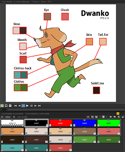
Using a Color Model
Color models, usually created for accurate color-referencing during a production, in the form of images or animation levels, can be used while painting animation levels.
Any image or animation level can be used as a reference by loading it in the Color Model viewer. In case an animation level is loaded, you can select any frame as a reference at any moment; in this way you can also create color models made of several drawings, for example one drawing for the Front view of the character, and one for the Back view.
When a color model is loaded for the current level, you can decide to load its palette, thus overwriting the current level palette, or to keep the current animation level palette.
If the color model is a Smart Raster or Vector level (TLV or PLI file), it already comes with a palette, whose style names and page configuration will be preserved.
If the color model is a full-color Raster image or animation level, the palette is automatically generated by extracting colors from the image, or the first image of the level. If the full-color image contains many shaded colors, the palette will be optimized to reduce the number of colors.
Note
Best results can be achieved by preparing models painted with flat colors and whose lines have no antialiasing.
When a color model is loaded for a certain animation level, it is associated to that level and the related palette, and it’s displayed in the Color Model viewer every time that level is selected.
A color model can be associated to palettes stored in the Studio Palette. In this way every time you assign a palette to an animation level retrieving it from the Studio Palette, its related color model will be automatically associated to the level (see Using the Studio Palette for details).
You can also use any drawing belonging to the animation level as a color model to be used on the fly, but in this case it will neither be associated to the level, nor to the palette saved in the Studio Palette.
When the image is displayed in the Color Model viewer, you can use it not only as visual reference, but also for picking styles with no need to use the Palette or the Style Picker tool (). The color model can also be panned and zoomed in or out, by using standard shortcuts.
Tip
To load a color model:
Do one of the following:
Choose File → Load Color Model…, and load the Toonz level or the full color raster image you want to use as a reference.
Right-click in the Color Model viewer and choose Load Color Model from the menu that opens.
Drag and drop the Toonz level or the full color raster image you want to use as reference to the Color Model viewer.
Choose whether to overwrite current palette with the Color Model palette, or to keep the current animation level palette.
Note
If you decide to keep the current animation level palette, the current level palette will be applied to the Color Model as well.
Tip
To select a frame from the loaded color model level:
Do one of the following:
Use the playback buttons.
Drag the frame bar cursor.
Type in the frame bar field the number of the frame you want to view.
Tip
To pick styles from a color model:
Click the area or line whose style you want to pick, whatever your current tool is.
Note
If you are using a Raster image as reference and you decided to keep the current animation level palette, when you click an area or a line, the closest style available in the palette will be picked.
Tip
To navigate the color model viewer:
Do one of the following:
Use the zoom shortcut keys (by default + and - keys) to zoom in and zoom out at specific steps (e.g. 50%, 100%, 200%, etc.).
Use the mouse wheel to zoom in and zoom out.
Use the Reset View shortcut (by default the 0 key), or right-click in the viewer and choose Reset View from the menu that opens, to display the flipbook content at its actual size, centered on the image center.
Middle-click and drag to scroll in any direction.
Tip
To create a color model from an original drawing:
Scan and cleanup, or draw, your color model.
Create the needed styles in the palette and paint the image.
Save the image and load it as color model whenever it is needed.
Tip
To use a drawing from the current animation level as a model:
Select the drawing you want to use as a reference for the current animation level.
Right-click in the Color Model viewer and choose Use Current Frame from the menu that opens.
Tip
To store a color model together with a palette in the studio palette:
Load the color model to associate it to the current level palette.
Store the level palette in the Studio Palette (see Using the Studio Palette for details).
Tip
To associate a color model to a palette already saved in the studio palette:
In the Studio Palette select the palette to which you want to associate a color model, and do one of the following:
Choose File → Load Color Model….
Right-click the palette in the studio palette tree and choose Load Color Model… from the menu that opens (see Using the Studio Palette for details).
Retrieve the color model from the browser that opens.
Note
If the color model uses a palette different from the one stored in the Studio Palette, you will be prompted whether to keep it or to overwrite it.
Tip
To retrieve a color model stored in the studio palette:
Load the palette it’s associated to from the Studio Palette as the current level palette (see Using the Studio Palette for details).
Tip
To remove the association of a palette to a color model:
Right-click in the Color Model viewer and choose Remove Color Model from the menu that opens.