Creating Cutout Animation
Cutout animation is based on characters made of several sections connected together to create a character model. For example a basic model can be made of a drawing for the head, one for the body, one for each arm, and one for each leg.
Animations in this case can be created not by adding drawings depicting the new animated poses, but by transforming (i.e. moving or rotating) the model sections individually at different frames, in order to create different actions.

In Tahoma it’s possible to create links between a model’s different sections and to set pivot points for each one of them, in order to better manage the animation. For example, you can link a hand to an arm at the wrist, and link the arm to the trunk at the shoulder: in this way when you move the trunk, you will move both arm and hand as well; when you move the arm, it will turn around the shoulder and the hand will follow its movement; when you move the hand, it will turn around the wrist.
Tip
To create a cutout animation:
Place each section (that can be a single drawing or an animated level) of your character in a different column/layer.
Use the Skeleton tool (
 ) to link each section to the other and set the related pivot points.
Create keyframes for each section at different frames to animate the cutout character.
Using the Skeleton Tool
The Skeleton tool () allows you to define a model by setting hierarchical links between its different sections exposed in different Xsheet columns (or Timeline layers), and animate it.
It basically makes possible, by using a single and more immediate tool, the same tasks that could be achieved by using the Stage Schematic and the Animate tool ( ), when used to create links and animate the transformations of columns/layers (see Linking Objects ). Indeed, any editing performed with the Skeleton tool () can also be seen happening in the Stage Schematic and the columns/layers transformation values, and vice versa.
In the tool options bar you can set the following:
Mode sets the operation to perform with the tool. Options are: Build Skeleton, to create links between the different sections, Animate, to animate the character model, and Inverse Kinematics, to animate the character model using inverse kinematics.
Global Key when activated sets a key for all the object transformations as soon as a key is defined by animating the skeleton. This means that if you rotate a model section, automatically a key will be defined for the position, scaling and shearing transformations as well.
Show Only Active Skeleton when activated displays only the pivot points and the skeleton from the current section up to the parent section: in this way it will be easier to manage characters with skeletons of a higher complexity.
Building a Skeleton
When the Skeleton tool () mode is set to Build Skeleton, it’s possible to set pivot points and links between sections by using the handle available in the Viewer.
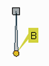
The handle is made of a small circle, with an arm that by default extends upwards. This allows you to perform the following tasks:
Click and drag the yellow circle to set the pivot point position.
Click and drag the square at the end of the extended arm to set the link to another section.
Note
The section pivot point can be moved, but cannot change its position during the animation: once it is set, or modified, it is retained during all the animation. If the pivot point is changed many times, and you want to set it back to its original position, right-click the section in the Stage Schematic and choose Reset Center from the menu that opens.
The handle refers to the current section; when you link a section to another, the link is graphically displayed connecting the centers of the two sections. When one or several sections are linked, all their links and the related centers, are displayed as well, configuring the skeleton for the model.
Creating Basic Models
A basic model is made of sections linked to each other by their centers. It’s simpler to create if compared to a model based on hooks (see Creating Models with Hooks ), and has some limitations, but it is suitable for most of the cases of cutout animation.
By default each section has a center that’s placed at the center of the viewer. When creating a model, this center has to be moved to where the pivot point for that specific section has to be.
The Skeleton tool () allows you, both, to change the center position of the currently selected model section, and to link it to the center of another section visible in the Viewer.
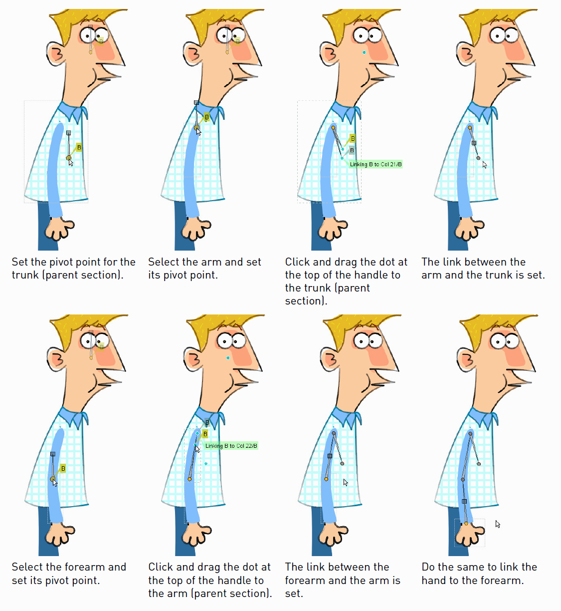
Usually it’s simpler to start working from the parent section, then link the other sections one by one, following one limb at a time. For example first set the center of the model trunk, then set the arm pivot point and link the arm to the trunk, then set the forearm pivot point and link the forearm to the arm, then set the hand pivot point and link the hand to the forearm, and so on.
In case the sections of your model are drawn in the right place, setting the pivot points and the links is all you have to do to define a skeleton. If they are not, you can set the section right position either before or after setting links by using the Animate tool or the Skeleton tool in Animate mode (see Animating Objects and Animating Models ).
Tip
To select a model section:
Select the Skeleton tool (), set the mode to Build Skeleton, and click the section in the Viewer.
Tip
To set the pivot point of the selected section:
Click and drag the yellow circle.
Tip
To Link the selected section to another section:
Click and drag the square at the top of the handle to the section you want to be parent. The section you drag to is highlighted by displaying its bounding box and a label displays information about the link you are going to create.
Release to set the link.
Tip
To Break the link between the selected section and its parent:
Click and drag the square at the middle of the graphical link between the linked sections away from the parent one.
Tip
To visualize only the skeleton from the current section up to the parent section:
Activate the Show Only Active Skeleton option in the tool options bar.
Creating Models with Hooks
Sometimes basic models may not produce the desired results because the positions of the pivot points in the skeleton are fixed, and therefore cannot follow the changes of model sections which are animated levels themselves.
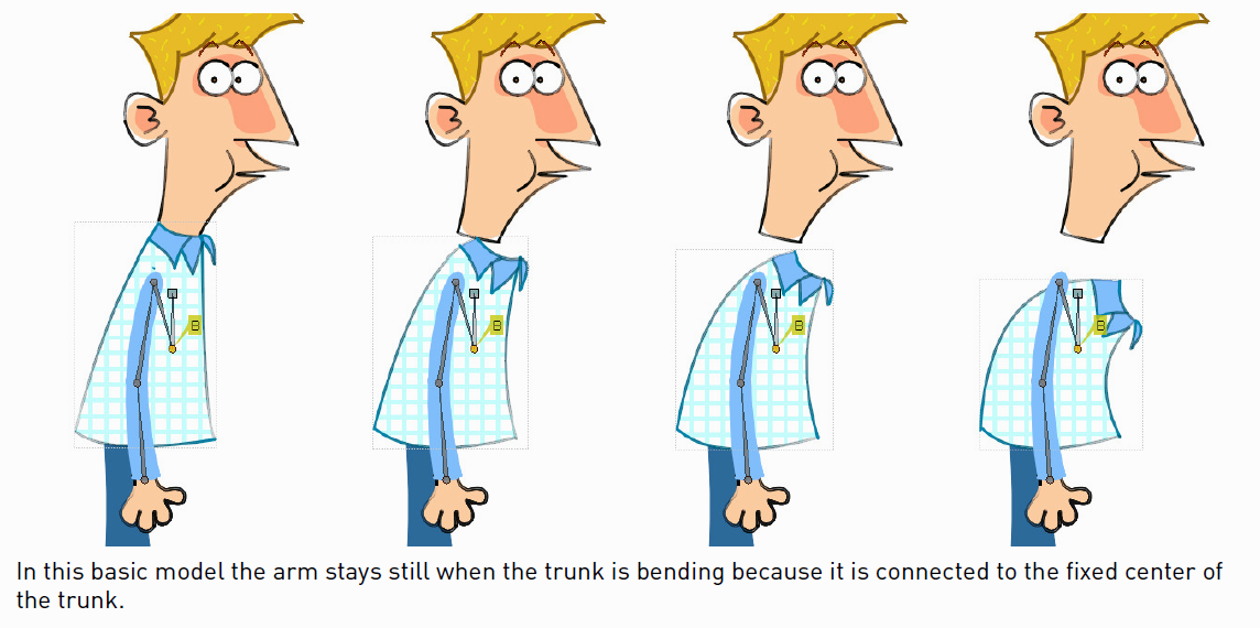
For example suppose you have a character whose trunk is an animated level made of several drawings of the trunk bending: as the animation of the trunk goes on, the limbs linked to it will not follow the movement of the trunk (because the trunk is neither moving nor rotating in terms of its transformation values).
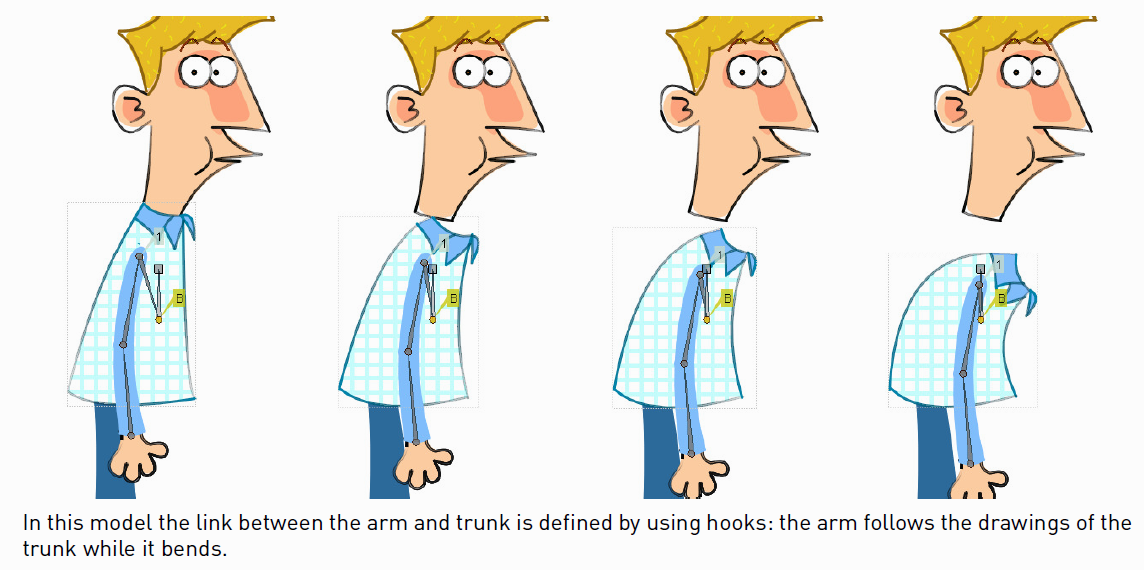
By using hooks you can specify, drawing by drawing, where the pivot points have to be placed: in this way the model will maintain its consistency even when different drawings from an animation level are used, during the course of the action (see Using Hooks ).
For example, by placing hooks on the drawings of the trunk and on the limbs (where they have to be connected), and defining the links by using hooks instead of centers, the limbs will follow the trunk even if it is bending.
The Skeleton tool () allows you, both, to set a hook as the pivot point for the section, and to link it to a specific hook of another section visible in the Viewer.
Hooks have to be placed for each character model section where you want the joints to be. For example, a trunk may have five hooks, one for the head, two for the arms and two for the legs; a forearm may have two hooks, one for the elbow and one for the wrist.
When using the Hook tool ( ) for defining hooks for the model sections, the Snap option can be activated (see Using Hooks ). In this way it’s possible to place hooks exactly in the same position of hooks already defined for other animation levels visible in the Viewer, or, in case the level is a Vector level, at the center of closed shapes (e.g. rectangles, circles or single vector shapes closed with the Tape tool).
This means that, in case the model sections are drawn in the right place, you can define perfectly overlapping hooks, so that limbs preserve their position when hooks are linked; or you can use regular shapes in Vector drawings (such as circles), to define the overlapping areas of the model limbs, and consequently place hooks exactly at their center to achieve a perfect match when hooks are linked.
Note
The hook number is just a label to identify hooks, and it is not relevant when performing links.
Usually it’s simpler to start working from the parent section, then link the other sections one by one, following one limb at the time.
When starting to build a skeleton with hooks, two different cases may take place: the model sections are not drawn in the right place, one in relation to another; or they are drawn in the right place one in relation to another.
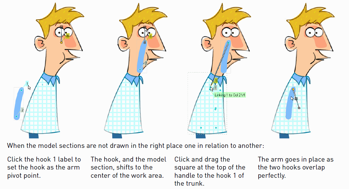
In the first case the appropriate hook has first to be set as the pivot point for the model section, then the link can be created. Note that when setting a hook as the new pivot point, the hook, and consequently the section, shifts to the center of the work area; as soon as you link that section to the hook of another section, it goes to the right place, with the two hooks perfectly overlapping.
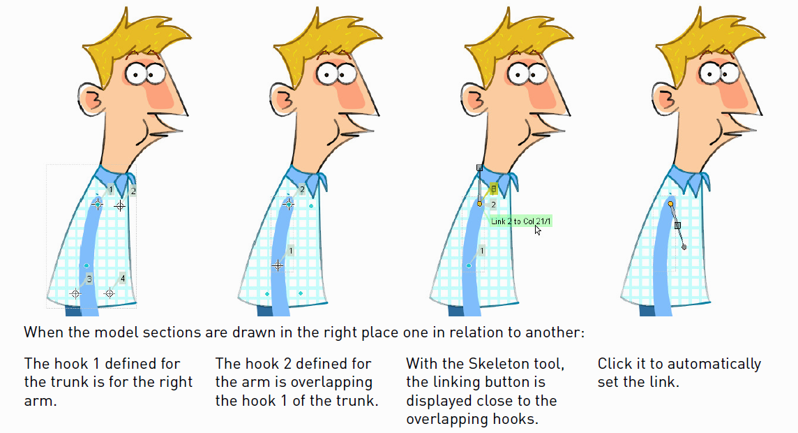
In the second case a hook of the selected section and a hook of another section are overlapping (e.g. the hook on the wrist of the hand section overlaps the hook on the wrist of the forearm section), and a special button displaying information about the overlapping hooks can be used to automatically link the two sections with a single click.
Tip
To select a model section:
Select the Skeleton tool (), set the mode to Build Skeleton, and click the section in the Viewer.
Tip
To set a hook as the pivot point of the selected section:
Click the hook label displayed close to the hook.
Tip
To Link the selected section to a hook another section:
Click and drag the square at the top of the handle up to the section you want to be its parent. All the hooks are displayed and the section you drag to is highlighted by displaying its bounding box.
Drag towards the hook you want to link the section to: the hook label is displayed and another label displays information about the link you are going to create.
Release to set the link.
Tip
To Link two overlapping hooks:
Click the label close to the overlapping hooks displaying information about the link you are going to create.
Tip
To Break the link between the selected section and its parent:
Click and drag the square at the middle of the graphical link between the linked sections away from the parent one.
Tip
To visualize only the skeleton from the current section up to the parent section:
Activate the Show Only Active Skeleton option in the tool options bar.
Animating Models
When the Skeleton tool () mode is set to Animate, it is possible to set positions for the model sections at different frames, thus defining an animation.
In the viewer it’s possible to select a model section and perform the following tasks:
Click anywhere to rotate the current section.
Click and drag the green square with the four arrows to move the current section.
Note
As you roll over the handle, the cursor changes shape to indicate to you the operations you may perform.
Every time a position for a section is set, a keyframe is automatically generated for the Xsheet column (or Timeline layer) where that section is exposed, at the current frame. Keys are created only for the transformation you modify: rotation, displacement, or both.
It is also possible to activate the Global Key option in order to set a keyframe for all the section transformations, including scaling and shearing, as soon as a keyframe for one transformation is set. This may result useful if you want to animate the model first, and then refine the animation by adding stretching and squashing transformations.
If you want to create a keyframe without operating the handle, in order to leave the section position and rotation as they are, you can use the Set Key button ( ) available in the bottom bar of the Viewer. In this case keys are created for all the object transformations (see Animating Objects ). It is also possible to manage keys for several model sections at once by inserting or deleting keys affecting the Xsheet/Timeline as a whole, or a selection of Xsheet columns (or Timeline layers) (see Working with Multiple Column Keys ).
Keys and interpolations you define in this way are displayed in Xsheet columns (or Timeline layers), where they can be directly managed (see Using Column Keys ).
As keyframes can be defined at specific frames for specific sections only, you may calibrate the animation and the movement speed of your model the way you prefer.
Note
Columns/layers can also be animated by working in the Function Editor (see Editing Using Spreadsheet and Curves )
In case a model section is an animation level consisting of several drawings instead of a single one (for example, if the character’s hand is an animation level consisting of drawings of the hand in different positions), the Skeleton tool () lets you also flip through the drawings to choose the one you need.
Tip
To Select a model section:
Choose the Skeleton tool (), set the mode to Animate, and click the section in the Viewer.
Tip
To Rotate the selected section:
Click and drag anywhere in the Viewer.
Tip
To Move the selected section:
Click and drag the green square with the four arrows available on the right of the current section pivot point.
Tip
To visualize only the pivot points of the current section up to the parent section:
Activate the Show Only Active Skeleton option in the Skeleton tool options bar.
Tip
To flip through the drawings belonging to the animation level:
Click the label with the level name on the right of the current section pivot point and flip through following and previous frames by doing one of the following:
Drag up or down.
Click the up or down arrowheads.
Using Inverse Kinematics
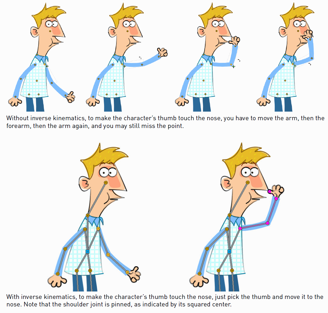
When the Skeleton tool () mode is set to Inverse Kinematics, it’s possible to move the model considering the articulation of all the sections its skeleton is made of. This means that if you want to move the end of a model limb to a particular position, all the rest of the sections belonging to that limb will move consequently, with no need to move each section separately.
For example, if you want the hand of a character to reach a particular point, you don’t need to animate the arm and the forearm separately, but instead you can move the hand to the final position, automatically adjusting the arm and forearm sections.
When the Inverse Kinematics mode is activated, the full skeleton with pivot points and links is displayed.
When moving the model, a rotation keyframe is automatically defined for all the sections involved in the movement, unless the Global Key option is activated thus generating a keyframe for all the section transformations.
Note
When using inverse kinematics the movements of the parent section of the skeleton are automatically computed to allow the right configuration of the skeleton; this means that they cannot be edited anymore by using standard movement editing tools like the Animate tool or the Function Editor. To return to the standard movement editing mode, you have to reset the pinned centers information.
Pinned Center
One single center (by default located on the section that is the parent of the skeleton), is displayed as a blue square: indicating that it’s pinned and its position won’t change throughout the animation when the character sections are animated.
The pinned center can be moved from a joint to another along the animation in order to have a center pinned only for a specific frame range. When the pinned center is changed at a specific frame, all the previous frames will retain the previously pinned center; all the following frames will have the new pinned center up to the frame where another pinned center position, if any, is defined in advance.
Changing the pinned center allows for a more complex animation where fixed points have to change while the model is moving, for example a walk where one ankle is pinned while the character is doing the first step, and the other ankle is pinned during the second step.
Note
Once the pinned center is defined, it will remain active when animating skeleton sections both with the Skeleton tool (), and with the Animate tool (). To freely animate any skeleton section again, reset the pinned center information (see below).
Temporarily Pinned Centers
Multiple additional centers can be temporarily pinned at any frame in order to constrain additional joints to a specific position. Unlike the pinned center, temporarily pinned centers are not preserved when the current frame changes, as they are used only to define the position of the sections at a certain frame.
Using temporarily pinned centers allows for the definition of specific poses at specific frames, for example the rising of an arm by pinning the shoulder joint.
According to the pinned center, and the temporarily pinned centers, it’s possible to click any point of any section and drag to move the model: all the parent sections up to the first pinned center along the skeleton will move consequently, while all the linked sections down to the free end of the limb will move rigidly with the picked section. The sections affected by the movement are highlighted by displaying the link wires in red.
The pinned centers information and coordinates are saved along with the scene; in case you want to delete it or start the animation by using the inverse kinematics from scratch, this information can be reset to the default, where only the center of the parent section of the skeleton is pinned.
Tip
To animate the model with Inverse Kinematics:
Choose the Skeleton tool (
) and set the mode to Inverse Kinematics.Click any point of any model section and drag it to the desired position.
Tip
To set the skeleton Pinned Center:
Ctrl-click the center: it turns from an orange circle to a blue square to indicate it is pinned.
Tip
To change the skeleton Pinned Center:
Select the frame where you want the new center to be set.
Ctrl-click the new center: all the previous frames will retain the previously pinned center; all the following frames will have the new pinned center up to a frame where another pinned center might have been defined in advance.
Tip
To set a Temporarily Pinned Center:
Shift-click the center: it turns from an orange circle to a light blue square to indicate it is temporarily pinned.
Tip
To unset a Temporarily Pinned Center:
Shift-click the temporarily pinned center: it turns from a light blue square back to an orange circle to indicate it’s no longer temporarily pinned.
Tip
To Reset the Pinned Centers information:
Choose the Skeleton tool (
).Right-click in the viewer and choose Reset Pinned Center from the menu that opens.